The Edit toolbar groups the buttons for the creation and modification of the model.
The Edit toolbar groups the buttons for the creation and modification of the model.
For the insertion of members, nodes, or dimension lines in Ftool, the program automatically snaps the mouse cursor to an existing unit (a node or a member). The creation process can be facilitated by enabling a Grid of points and using the Snap feature. (See Visualization Controls - Coordinate Control).
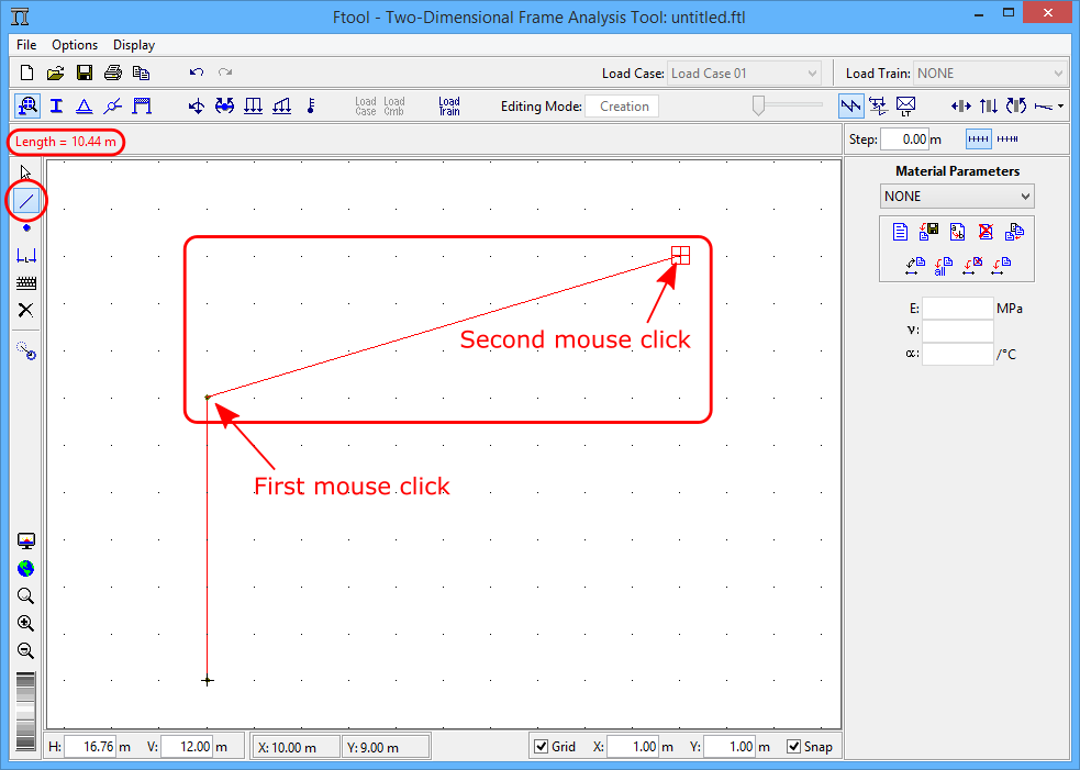
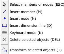
Member and node creation is straightforward. To insert a member, select the button
and click on two points within the model display area. Nodes are created instantly at the ends of the member. If the inserted member intersects an existing one, a new node at the intersection of the two members is created utomatically and the two members are automatically subdivided.
In the same way, a node is created by selecting the button
and clicking with the mouse at a point within the model display area. If the clicked point is on an existing member, the member is divided in two members with insertion of the new node.
The insertion of "lines" with the mouse for creation of members is made with two clicks: one for the first node of the member and the next click for the second node. Usually the creation of lines using a mouse follows the rule "press button - drag mouse – release button". The "two clicks" method used in Ftool allows the user to stop the insertion of members after the first point by clicking with the right mouse button or by pressing Esc on the keyboard. This type of method also allows the user to zoom in or move the drawing window after entering the first node and before entering with the second, etc.
The coordinates of the mouse cursor position are indicated in a text box located in the bottom of the screen. (see Visualization Controls - Coordinate Control). While a member is inserted, prior to the second mouse click, a message bar on the top of the screen displays the member length.
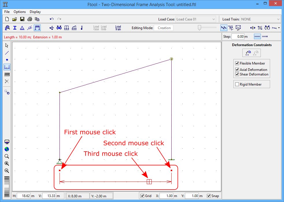
Dimension Lines are auxiliary lines used to indicate distances on the structural model. To insert a dimension line, select the button
in the Edit toolbar and click three points on the screen. The two first points are the control points to specify the distance to be listed by the dimension. The third point defines where the dimension line will be located. During the construction of the line, the program updates the dimension line on the screen until the user enters the third point.
The creation of a dimension line through the "three clicks" method allows the user to suspend the insertion of the line before entering the final points, by clicking with the right mouse button or by pressing Esc on the keyboard. This type of interaction also allows the user to zoom in or to move the viewing window after entering the first point or the second point and before entering the third.
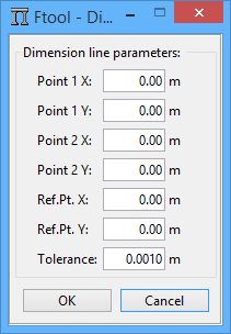
The
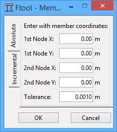
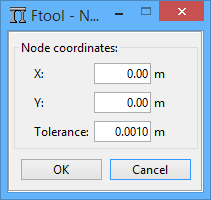
button toggles keyboard mode. When it is active, when a user tries to create a member, node or dimension line with the methods described above, a dialog will appear where they can define the element’s desired coordinates. The Tolerance value is used for the "attraction" of existing nodes/members (never use null value for tolerance). When “OK” is clicked, the dialogs appear again, allowing the user to create yet another element. In the case of members, the new dialog appears with values which describe a collinear member of same length, therefore allowing for a quick creation of sequential collinear members.
The button
turns on "selection" mode. In this mode, right-clicking the mouse on a member or node displays its attributes in a menu on the side of the screen. Use the left button to select an item (the program never allows members and nodes to be selected simultaneously).
The selection of a set of members or a set of nodes can be made by clicking the left button of mouse concurrently with the SHIFT key. With the key pressed, clicking on an already-selected element deselects it.
A set of members/nodes can also be selected by defining an enclosing rectangle. To do this, press and hold the left button of the mouse and drag it to define the rectangle. Release the mouse button to complete the rectangle. If the rectangle is drawn from left to right, it is red and all elements contained entirely in the rectangle are selected. If drawn from right to left, the rectangle is green and all elements either contained within or intersected by the rectangle are selected. If the SHIFT key is pressed and some elements are already selected, then only elements of the same type (beam or node) will be selected. Otherwise, the program first attempts to select members; if none are found, vertexes contained by the rectangle are then selected.
Once nodes and members are selected, actions can be executed upon them. To delete entities push the
button. To transform the selected entities, use the Transform button (see Transformations). The user can also apply attributes or loads to the selected members or nodes – this is discussed later.
The Undo option cancels previous actions. The Redo option re-executes the last cancelled action.
The following actions can be undone:
- Creation or deletion of members, nodes and dimension lines;
- Transformations of members, nodes and dimension lines;
- Application of a property (member materials, cross-sections and deformation constraints, nodal supports and releases) to members or nodes;
- Application of static loads (nodal concentrated forces, member end-moments, distributed and thermal loads);
- Creation and deletion of load cases and combinations (Advanced Edition);
- Modifications to a load combination (adding or removing included load cases or editing factors) (Advanced Edition).
The following actions reset the undo list (doing these will not allow the user to undo previous actions, including the action itself):
- Deletion of properties and loads that were once applied to elements of the model;
- Entering result-visualizing mode (actions such as transformations taken once already visualizing results enter the list).
The Redo button can only execute the last undone action. Therefore, if multiple actions are undone, all but the last action are lost.
If the user selects the Transform button, the multi-purpose area to the right of the canvas presents the transformation options. If no object (member, node or dimension line) is selected, the area will be disabled. If the user selects one or more objects, the Enable Transform option becomes available for selection. Once triggered, the user may begin performing transformations on the selected objects.
Four transformations are available: translation (Move), rotation, scaling and mirroring. The desired transformation is defined by selecting the appropriate tab.
Transformations present three options, two of which are mutually exclusive. These are: to forbid the transformation from altering the structure’s topology (therefore forbidding new intersections, for example) (Maintain Topology), and to leave the original object (creating therefore a copy in the new position) (Leave Original). The user may choose to disable both options or to activate one – it is not possible for both to be selected simultaneously. If Maintain Topology is selected, the user may not perform mirroring transformations. Another option is to deselect all objects after the transformation (Deselect after transform). By default, this option is disabled, meaning that objects will remain selected after the transformation.
Transformations may be performed either by mouse or keyboard. The "keyboard mode" defined on the column to the left of the canvas is not relevant for transformations. The operation to be performed depends on the desired transformation:
- Translation:
- Mouse: The user clicks once on the canvas to define the origin of the translation, drags the mouse and then clicks once more to define the end of the translation.
- Keyboard: The user defines the horizontal (DX) and vertical (DY) translation and then clicks the Forwards button to apply the transformation.
- Rotation:
- Mouse: The user clicks once to define the origin of the rotation, drags the mouse, clicks again to define the beginning of the rotation arc, drags the mouse, and clicks once more to define the end of the arc (and therefore the angle of rotation).
- Keyboard: The user defines the coordinates of the center of rotation (X and Y) and the angle and then clicks the Forwards button to apply the transformation.
- Scaling:
- Mouse: The user clicks once to define the origin of the scaling, drags the mouse, clicks again to define a reference vector, drags the mouse, and then clicks once more to define the transformed vector and therefore the scaling factor (equal to the ratio of the lengths of the transformed and reference vectors).
- Keyboard: The user defines the coordinates of the scaling center (X and Y) and the scaling fator and then clicks the Forwards button to apply the transformation.
- Mirroring:
- Mouse: The user clicks once to define a point, drags the mouse, and then clicks once again to define the mirroring line.
- Keyboard: The user defines the coordinates of two points along the mirroring line (X1, Y1, X2 and Y2) and then clicks the Forwards button to apply the transformation.
Another available option when performing transformations with the keyboard is to use the Back button, which applies the inverse transformation (for example, if the user defines a 15° rotation and clicks Back, the rotation will be of -15°).
If Maintain Topology is disabled, when performing transformations with the mouse the user will see a feedback which displays the final positions of the transformed objects. The objects themselves, however, are not modified until the end of the transformation. However, if Maintain Topology is selected, the objects are transformed immediately and therefore "follow" the mouse. With this option selected, it is suggested that the user move the mouse slowly.
Every transformation must respect a given tolerance. If the transformation is defined via the keyboard, the adopted tolerance must be defined in the given textbox. In this case, the default tolerance is equal to the smallest possible value for the current length format (1, 0.1, 0.01, 0.001, etc) or, in the case of exponential formats, 1.0e-4. For more details regarding numbering formats, see Configurations - Formatting Units and Numbers. If the transformation is done via the mouse, the Tolerance textbox is ignored and the tolerance is defined internally as a function of the zoom scale of the canvas.
With one of the textboxes (translation’s DX or DY, for example) selected, one may also use the following keyboard shortcuts: Enter to apply the current transformation or Ctrl+Enter for the inverse transformation.
Transformations may also be done while displaying static results, the structure’s deformed configuration or influence lines. In these cases, the transformation must maintain the structure’s topology. All diagrams are automatically updated maintaining their scale. See the relevant subsections in Results for further details.
Another available transformation is to modify member orientations (Invert member orientation). When members are selected (while not displaying results), this option becomes available and allows the member orientations to be inverted. This option can be useful when dealing with loads applied in the members’ local axes.