Advanced Edition
Ftool has a commercially available advanced edition with additional
features.
To access Ftool’s advanced edition, the user must first purchase a license.
That can be done from the Ftool’s website after registering. Upon purchase,
the user will receive an email with the license’s serial key. The serial can
also be seen in the user’s account page on the Ftool website.
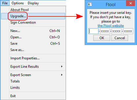
Clicking on File > Upgrade..., will open a dialog window where the
serial key must be given. An internet connection is required for this
operation, since the key will be validated by the Ftool servers.
After validating the new license, Ftool will close. Once reopened, it will
initialize itself with the Advanced Edition. On subsequent uses, the program
will open in the Advanced Edition so long as the license is valid. Every time
it opens, Ftool will try to connect to its servers to validate the license. If
the servers cannot be accessed due to a lack of an internet connection or some
other reason, the program will keep working in the Advanced Edition for thirty
days and/or ten uses of the program. That is, if the program is not used for a
long time and then an attempt to use it cannot connect to the servers, the
license will still be considered valid for the next ten uses.
When the serial key is validated, a file called Ftool.license is created in
the same directory as the Ftool executable (Ftool.exe). This file must always
be kept in the same folder as the executable. If the license file isn’t found,
the program will revert to the free edition. The license is also bound to the
current computer. If you wish to have the Advanced Edition in more than one
computer, multiple licenses must be purchased.
The save-files created by the Educational and Advanced Editions are the
same and perfectly compatible. However, if the Advanced Edition is used to
create a model with multiple load cases and/or load combinations and this
model is then opened with the Educational Edition, a warning will appear
informing the user that only the first load case will be accessible. The model
may be modified, calculated and saved normally; the hidden load cases and
combinations will not be lost.
The free edition of Ftool always opens with certain configurations: units
in the SI system and values displayed with formats according to the
Units and Number Formatting window,
displaying dimension lines but not reactions, disabled grid, and so on. The
Advanced Edition, however, allows the user to define these initial
configurations easily.
To do so, the user must simply configure the program as they wish the
program to be initialized and then go to Options > Save current properties
as default. A popup will appear to confirm the operation. If confirmed,
the properties will be saved in the file Ftool.properties and will already be
used to reset the configurations if the user chooses to start a new model.
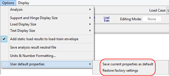
To return to the default values for all the configurations, simply select
Options > Restore factory settings. Once again, a popup will appear to
confirm the operation.
The Ftool.properties file is created in the same directory as the Ftool
executable (Ftool.exe) as soon as the license is initially validated and must
be kept in the same folder as the executable. If the file is not found, the
factory default configurations will be adopted and a new Ftool.properties file
will be created with these factory defaults.
The Ftool.properties file is quite self-explanatory, so users are invited
to explore it to see all the options which may be configured. In summary,
these include:
- whether the grid is active, whether the mouse should snap to it, and
its spacing;
- whether to start in Keyboard Mode;
- the desired result mode (diagram, influence line, etc);
- the result step and whether it should be normalized;
- whether to add static loads to the load train envelope;
- whether to save the .POS file;
- the background color;
- what to display (dimension lines, reactions, loads, loads withresults,
step values, etc);
- the size to display supports, loads and text;
- units and number formats.
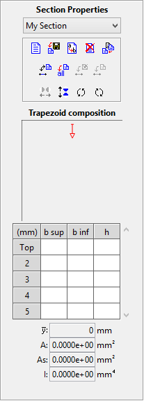
The Advanced Edition also includes a new cross-section, called
"User-built". This section can be used to describe any polygonal
cross-section that isn’t adequately represented by the parameterized sections.
The user describes the section as a composition of trapezoids by defining each
trapezoid’s height and top and bottom widths. The section is always symmetric
around its natural vertical axis. As trapezoids are added, a to-scale sketch
of the section is drawn, allowing the user to validate that the correct
dimensions were inserted.
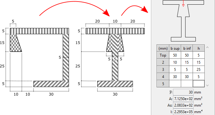
Since Ftool only uses the moment of inertia around the horizontal axis,
cross-sections which are hollow and/or are not symmetric around the vertical
axis can still be accurately modelled with this method by lumping all the
widths at a given height into an equivalent section of equal area and moment
of inertia (around the horizontal axis). For example:
The data matrix initially displays five rows, but the user may use as many
as required. When the last row is filled, an additional row is created below
it. To delete a row, merely select it by clicking on the row’s identifier
("Top", for example) and press the Delete key on your
keyboard.
This section can be rotated and flipped. The red arrow representing the
natural "Top" of the section is also transformed in this manner,
allowing the user to clearly identify the section’s current orientation and
therefore where new trapezoids will be added to the section. It is worth
remembering that for "equivalent sections" such as the one described
above, the rotated equivalent section will not accurately represent the true
section’s moment of inertia. Equivalent sections should always be defined
according to the real section’s actual orientation.
Firstly, Ftool makes use of the following terminology:
-
Loads
A load is an external solicitation applied to a structure. Ftool
offers the following types of solicitations: nodal concentrated forces
and moments, member-end concentrated moments, uniformly and linearly
distributed forces, thermal loads and load-trains. Each instance of a
load (for example, a vertical nodal force of -10kN) can be applied to
multiple elements of the structure.
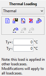
With the exception of load trains, loads are always applied within a
load case. The same load may be applied in more than one load case. In
such an event, however, any modification to the load will apply to all
load cases. Therefore, should the user select a load that is already
applied in another load case, the following warning will be
displayed:
-
Load cases
A load case is a collection of loads that always act simultaneously.
For example, a building will usually have a few different load cases,
such as:
- SW: The building’s self-weight, which may collect a series of
distributed loads representing the self-weight of the building’s
component parts (beams, slabs, columns, etc) and concentrated loads
representing the forces brought by beams perpendicular to the
current plane, among others;
- DL: Dead loads due to fittings and finishes;
- LL: Live loads due to occupation;
- Wi: Multiple cases for wind loads under different conditions and
faces of the building;
A model always has at least one load case and all loads are applied
to the structure within the current load case. For more details, see
Load Cases.
-
Load combinations
A load combination is a collection of load cases that may act
simultaneously. For example, a building may have a few different load
combinations, such as:
- The building’s self-weight, dead load and live load (SW + DL +
LL), for maximum column compression;
- Multiple combinations for the building’s self-weight, dead load
and each of the wind cases (SW + DL + Wi), for maximum column
bending;
- Multiple combinations for the building’s self-weight, dead load,
live load and each of the wind cases (SW + DL + LL + Wi), for
maximum column combined compression and bending.
Structural codes often require safety factors to be applied according
to a load case’s classification (dead load, live load, wind load, etc).
Ftool allows the user to define a multiplication factor for each of the
cases in a combination (for example, 1,35 x (SW + Dl) + 1,5 x LL + 1,4 x
Wi). For more details, see Load
combinations.
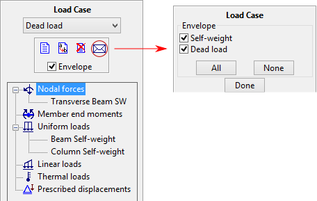
This sub-menu allows the user to see the loads included in each load case.
By clicking once on a specific load in the list, all elements that have the
load applied are selected. By double-clicking on a load in the list, the
relevant load-editing menu is opened. The user may also control which load
cases are included when visualizing load case envelope results. This can be
done by clicking the Envelope, checkbox, which toggles whether or not
the current load case is included, or by clicking the
 button, which opens a menu where the user
can modify whether any load case is included.
button, which opens a menu where the user
can modify whether any load case is included.
Like most other menus, when visualizing results, this menu is mostly
disabled. Only the Envelope checkmark and the
button remain active, allowing the user
to select which load cases are included in the load case envelope results.
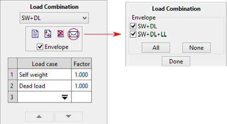
This sub-menu allows the user to define load combinations. The user may add
a load case by double-clicking on the Load case cell of the matrix’s
first unused line, which opens a dropdown menu with all the load cases not
already included in the combination. The combination then adds the selected
case with a default factor of unity. This factor can be modified at any time.
The format of the factor can be modified in the Units and Number
Formatting window. Load cases can also be removed from a combination by
selecting the desired matrix rows and pressing the Delete key on the
keyboard.
As load cases are added or removed and factors are modified, the current
combination’s resultant loading throughout the model is displayed on the
canvas.
The user may also control which load combinations are included when
visualizing combination envelope results. This can be done by clicking the
Envelope checkbox, which toggles whether or not the current load
combination is included, or by clicking the
button, which opens a menu where the user
can modify whether any load combination is included.
While the other menus are disabled when visualizing results, this menu
remains enabled. This allows the user to create, edit or delete load
combinations while displaying results. The results are updated automatically
with every modification to the combination.
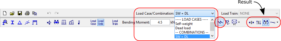
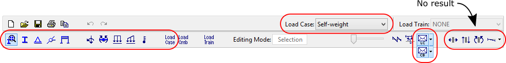
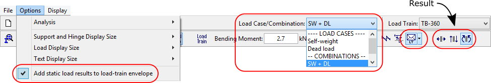
The dropdowns at the top-right corner of the window can be used to select
the current static load (load case or combination) and load train. Depending
on the situation, one, none or both of these dropdowns may be disabled.
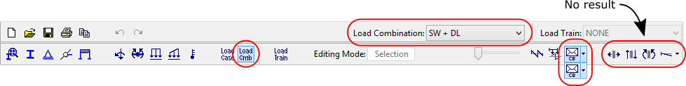
If in the Diagram result mode but not seeing results, the static
load dropdown will only list load cases. The only exception is if in the
Load Combinations menu, in which case only load combinations will be
listed. If seeing results, the dropdown will contain both cases and
combinations.


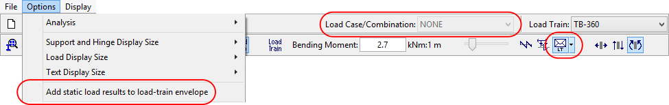
If in the Influence Line Line result mode (whether or not seeing
results), the static load dropdown is disabled and displays
"NONE".

If in the Load Case Envelope or Load Combination result modes
but not seeing results, the static load dropdown will only list load cases.
The only exception is if in the Load Combinations, menu, in which case
only load combinations will be listed. If seeing results, the dropdown will be
disabled and display "Envelope".


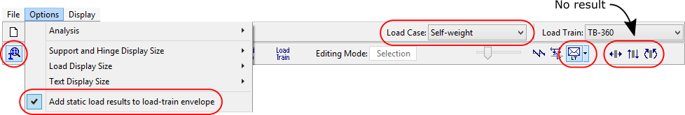
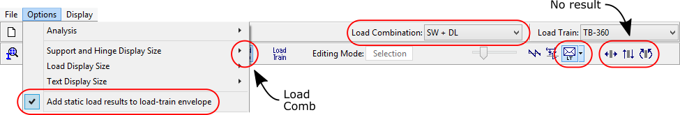
If in the Load Train Envelope result mode but not seeing results and
the Add static load results to load-train envelope option is active
(see Superposition of static load and
load-train results), the static load dropdown will only list load
cases. The only exception is if in the Load Combinations menu, in which
case only load combinations will be listed. If seeing results, the dropdown
will list load cases and combinations. Whether or not seeing results, if the
Add static load results to load-train envelope option is disabled, the
static load dropdown will also be disabled and display "NONE".
The load train dropdown menu is only active if in the Influence Line
or Load Train Envelope result modes or if in the Load Train menu. If
active, it includes all the current load trains and a "NONE". If
disabled, simply displays "NONE".


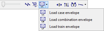
In the Advanced Edition, two additional result modes are added: Load
case envelope and Load combination envelope. These are selected via
a dropdown which also includes the standard Load train envelope mode.
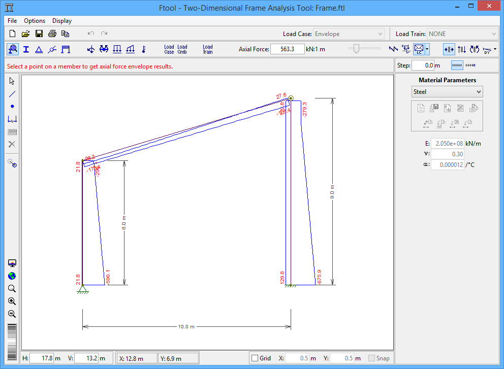
The Load Case Envelope and Load Combination Envelope modes
are used to display envelopes of limiting internal force values along a
structure under multiple static loads. Envelopes are diagrams of minimum and
maximum values of an internal force (axial, shear or bending moment) or
deformed configuration for the given static loads (either load cases or
combinations).
Only load cases or combinations that have been marked will be included in
the envelope (see Load Cases and
Load Combinations). If no case/combination
is toggled to be included in the envelope, a warning will be displayed and the
case/combination envelope menu will open. Should the user try to see load
combination envelopes before defining any combinations, the program will
display a message informing the user and the load combination menu will
open.
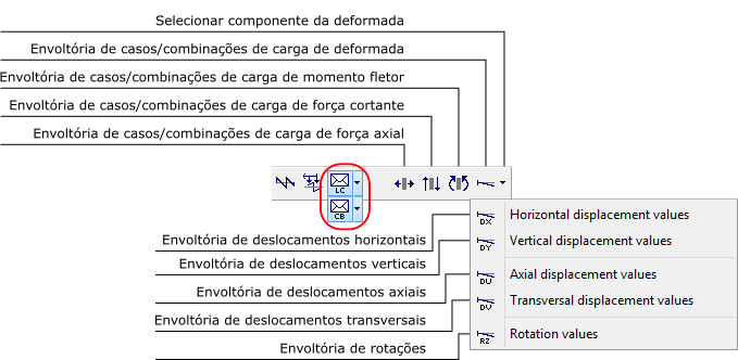
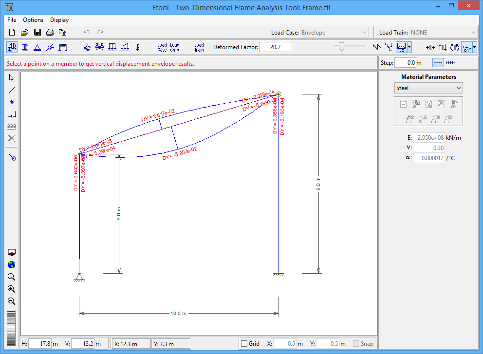
For the deformed configuration envelope, the user must select which of the
deflection components to print with the envelope: the horizontal, vertical,
axial or transversal displacement. The envelope displays only the maximum and
minimum values at each point for the selected component and therefore cannot
be taken as representing the true deformed configuration.
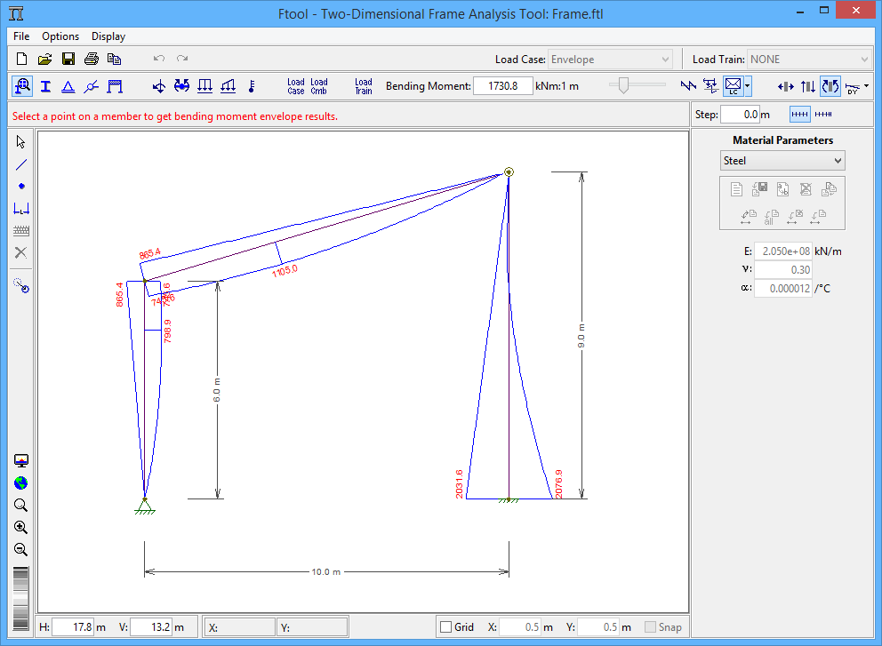
Point results of static load envelopes may be obtained by just selecting a
target position using the left mouse button. The minimum and maximum values at
that point are shown in the top message bar.
In these modes the user may apply transformations that do not alter the
structure’s topology (see
Transformations). To do so, the user
must open the transformations window, select the desired objects and then
apply the transformations. The results are automatically updated, maintaining
their scale.
| Vertical component of deformed configuration load
case/combination envelope |
 |
| Axial force load case/combination envelope |
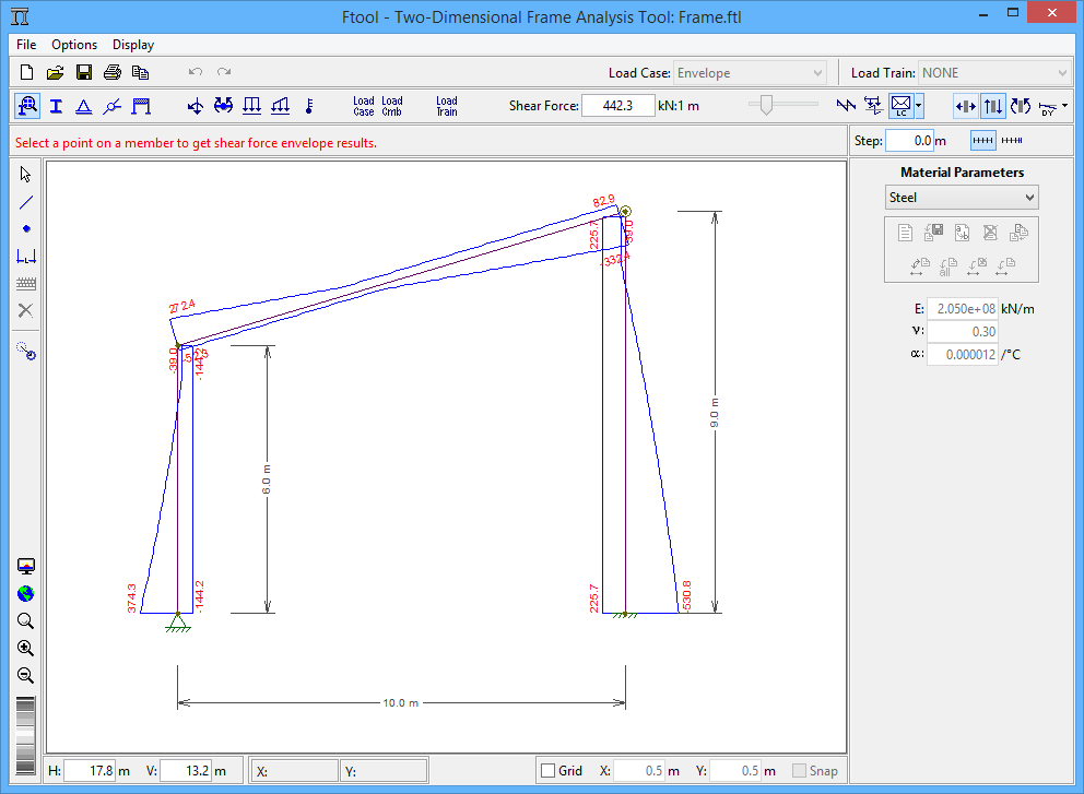
Shear force load case/combination envelope |
Bending moment load case/combination envelope |
 |
 |
 |